FAT3 Media Galleries
Completion requirements
CH29: Hydraulically Controlled Transmissions
Chapter 01 Strategy Based Diagnostics
|
2-3 Shift Valve Operation
|
3-2 Kickdown
|
Gear Position
|
||
|
Governor
|
Governor Pressure
|
Hydraulic Circuit Operation
|
||
|
L1 and L2
|
Modulator Valve
|
Operation of Hydraulic Controlled Transmission
|
||
|
Operation of BW35
|
Regulator and Control Valves
|
Reverse CVT
|
||
 |
||||
|
Shift Valves
|
The components of a Lock-up Torque Converter
|
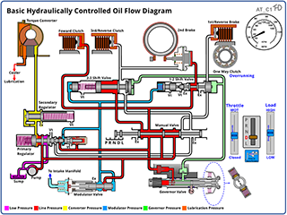
Basic Hydraulically Controlled Transmission Oil Flow Diagram
|
||
 |
 |
 |
||
|
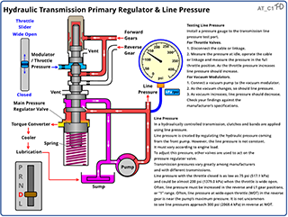
Hydraulic Transmission: Primary Regulator & Line Pressure
|
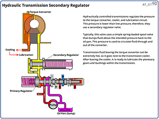
Hydraulic Transmission: Secondary Regulator & Converter Pressure
|
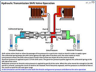
Hydraulic Transmission: Shift Valve Operation |
||
 |
 |
 |
||
|
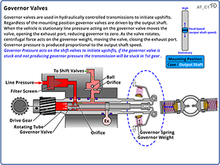
Governor Valves
|
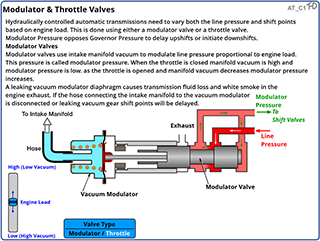
Modulator & Throttle Valves
|
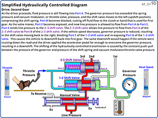
Simplified Hydraulically Controlled Diagram
|
||
 |
 |
 |
||
|
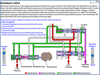
Kickdown Valve
|
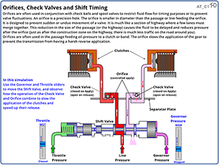
Orifices, Check Valves and Shift Timing
|
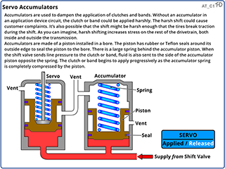
Servo Accumulators
|